
Choosing the right Electric Damper Actuator affects airflow control, energy use, comfort, and equipment life. A poorly matched actuator may stall, move slowly, or fail during critical operating conditions. The correct choice begins with the damper’s torque requirement, blade size, pressure, and movement angle.
Check the actuator’s voltage and control signal carefully. Common options include on-off, floating, and proportional control. Confirm whether the system requires spring return, non-spring return, or a fail-safe position. Small details matter. A crowded mechanical room can make installation difficult, especially when access is limited behind ductwork. The actuator should also suit the surrounding temperature, humidity, enclosure rating, and expected operating cycles.
Reliable selection depends on practical verification, not attractive specifications alone. Compare the manufacturer’s torque data with real damper resistance, including friction and airflow pressure. Review wiring diagrams, mounting instructions, service access, and tested compatibility with the building automation system. Independent certifications and clear technical documentation can strengthen confidence, but they do not replace correct installation and commissioning. A simple checklist helps, yet it may miss unusual site conditions. Engineers and technicians should measure where possible, then confirm assumptions with the supplier. In practice, the “strongest” model is not always the best choice. An oversized actuator can increase cost and installation strain, while an undersized unit may shorten service life. This guide explains the key decisions, common mistakes, and practical checks needed to select an Electric Damper Actuator with greater confidence.
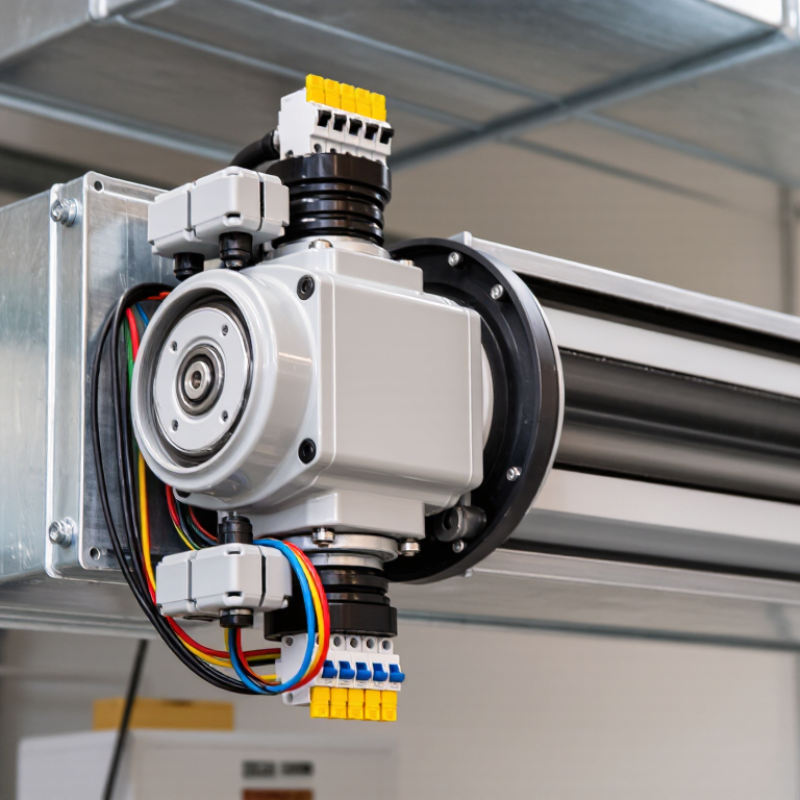
An electric damper actuator is a motorized device that moves an HVAC damper inside an air duct. It converts electrical energy into controlled rotary motion. The actuator connects to the damper shaft and turns the blades to regulate airflow. A thermostat, building controller, or sensor sends the operating signal.
The working process is simple, but selection requires care. A two-position actuator drives the damper fully open or closed. A modulating actuator adjusts the blade angle gradually, such as opening to 40% when a room needs moderate airflow. Some models include spring return. If power fails, the spring moves the damper to a preset safe position. That matters in smoke control and ventilation systems.
Check the damper’s required torque before choosing an actuator. Dust, pressure, blade size, and shaft friction can increase resistance.
Voltage and control type must also match the installed system, such as 24-volt power or a proportional signal. During commissioning, technicians should inspect rotation direction, mounting strength, and feedback accuracy. Small details matter.
I have seen installations fail because the actuator had enough power on paper, but the shaft connection slipped. It is worth testing the complete damper assembly, not only the motor. An enclosure rated for the surrounding moisture and temperature improves reliability. I would also avoid choosing the cheapest option automatically; service access and replacement time deserve attention. Mistakes happen, even in careful projects.
How to Choose the Right Electric Damper Actuator?
The damper type determines how the actuator should work. Parallel-blade dampers provide strong opening force, but they may create uneven airflow. Opposed-blade dampers usually regulate air more evenly. Butterfly dampers suit round ducts and compact spaces. Check the damper shaft torque, blade seals, air pressure, and temperature before selecting an actuator. A unit that seems powerful enough may still stall when seals become stiff or dirty. I have seen this mistake during maintenance reviews.
The control method must match the building system. On/off control works for simple ventilation zones. Floating-point control offers smoother positioning with three control wires. Modulating control, such as 0–10 V or 2–10 V, supports precise airflow adjustment. Choose spring-return operation when the damper must move to a safe position after power loss. Non-spring-return actuators can be suitable where this response is unnecessary. Do not assume the actuator’s feedback signal proves correct airflow. It only confirms shaft position.
Tips: Measure the actual damper torque when possible. Allow extra capacity for friction, dust, and aging seals. Confirm the actuator’s rotation angle and mounting pattern. Test the full stroke after installation. A control signal can look correct while the blades remain partly blocked. Recheck the selection after seasonal operation, because real duct conditions often differ from design estimates.
How to Choose the Right Electric Damper Actuator?
Matching an electric damper actuator starts with torque, not voltage. ASHRAE’s HVAC Handbook recommends considering blade friction, air pressure, seals, linkage geometry, and temperature. In field commissioning, I still see a familiar mistake: installers select torque from damper size alone. That shortcut fails when filters become dirty or duct pressure rises. The IEA and UNEP’s 2023 Global Status Report states that buildings consume about 30% of global final energy. Accurate damper control therefore affects more than comfort.
Use damper test data before choosing actuator torque. AMCA 500-D provides laboratory methods for evaluating damper airflow and pressure performance. Match the actuator’s rated torque with the damper’s measured breakaway and running torque. Add a practical reserve, often 25% to 50%, after checking the manufacturer’s test conditions. More reserve is not always better. Oversizing can reduce control sensitivity and increase cost. Confirm the actuator can complete the required movement within the control sequence. A 90-degree stroke in 30 seconds may suit ventilation, but smoke-control applications require different response criteria.
Operating range deserves equal attention. Check minimum and maximum ambient temperature, humidity, cycling frequency, supply voltage, and fail-position behavior. Torque ratings often use room-temperature conditions. Cold seals can demand more force. I learned this after a winter commissioning issue that looked like a wiring fault. It was not. The actuator lacked cold-weather torque capacity. Review derating curves, end-stop accuracy, and feedback resolution. Then compare those details with the actual pressure and temperature profile, not an ideal datasheet example.
Match actuator torque, operating speed, and temperature range to the damper’s size, pressure, and duty cycle.
| Reference Damper Profile | Recommended Torque | Typical 90° Running Time | Typical Operating Range |
|---|---|---|---|
| Small, low-pressure damper | 5 Nm | 60 seconds | −20°C to 50°C |
| Medium commercial damper | 10 Nm | 30 seconds | −20°C to 50°C |
| Large or higher-pressure damper | 20 Nm | 15 seconds | −20°C to 50°C |
| Extra-large or high-pressure damper | 40 Nm | 15 seconds | −20°C to 50°C |
Select an actuator with a rated torque above the damper’s calculated breakaway and running torque, including a practical safety margin. Larger blade areas, higher static pressure, shaft friction, seals, and linkage losses increase the required torque. Choose a faster actuator only when the control sequence requires rapid positioning; otherwise, a slower actuator can reduce mechanical stress and improve modulation stability. The values shown are general engineering reference ranges and should be verified against the damper manufacturer’s torque calculation.
When selecting an electric damper actuator, start with the damper’s real torque requirement, not its appearance. Field checks should include blade condition, shaft friction, linkage geometry, and airflow resistance. A useful practice is measuring breakaway torque, then adding a sensible service margin. Too little power causes stalled movement and overheating. Too much power can damage blades, seals, or the frame. Check running time, control signal, voltage tolerance, and duty cycle. A 24-volt unit may suit building controls, but the system design determines suitability. Confirm current draw against the controller and backup supply. Small mismatches create large maintenance problems.
Safety deserves equal attention. Select spring-return or non-spring-return operation according to the required emergency position. Verify electrical insulation, overload protection, manual override, and end-stop performance. I have seen installations fail because the actuator moved correctly but could not reach its commanded position. Environmental ratings matter just as much. Review the IP or equivalent enclosure rating for dust and water exposure. Check operating temperature, humidity, condensation, ultraviolet exposure, and corrosive air. Outdoor or coastal equipment may need stronger protection than an indoor rating suggests. Do not treat a rating as permanent protection. Gaskets age, cable entries loosen, and maintenance is often delayed. Use applicable local electrical requirements and the manufacturer’s tested installation limits. A careful site survey still beats a perfect catalogue specification.
| Selection Dimension | Typical Options / Values | How to Select | Why It Matters |
|---|---|---|---|
| Power Supply | 24 V AC/DC; 120 V AC; 230 V AC | Match the actuator voltage and frequency to the available control-panel supply. Do not connect a low-voltage actuator directly to a line-voltage circuit. | An incorrect supply can cause failure, overheating, electrical hazards, or loss of control. |
| Torque Requirement | Common actuator ranges: approximately 5–40 N·m for small to medium dampers; higher values for large or high-resistance dampers | Use the damper manufacturer’s required torque. Include friction, blade seals, duct pressure, linkage losses, and a reasonable safety margin. | Insufficient torque may prevent full closure or opening; excessive oversizing can increase cost and energy use. |
| Control Signal | Two-position; floating/three-point; proportional 0–10 V DC or 2–10 V DC | Select the signal type supported by the building-management system, controller, or thermostat. | Signal incompatibility can result in incorrect positioning, unstable operation, or no response. |
| Fail-Safe Function | Spring-return; electronic fail-safe; non-spring-return | Use spring return where the damper must move to a defined safe position after power loss. Specify the required fail position: open or closed. | Fail-safe behavior supports smoke control, freeze protection, ventilation, and equipment protection strategies. |
| Running Time | Approximately 30–150 seconds for a 90° rotation; faster models may be available for special applications | Choose a speed that meets the control sequence without causing excessive pressure changes, noise, or mechanical shock. | The wrong speed can reduce comfort, disturb airflow, or conflict with fire and smoke-control sequences. |
| Position Feedback | Auxiliary switch; 2–10 V DC feedback; potentiometric feedback; none | Specify feedback when the controller must verify damper position, provide interlocks, or report faults. | Feedback helps confirm operation and can prevent fans or heaters from running in an unsafe damper position. |
| Ingress Protection | IP20–IP30 for protected indoor areas; IP54 or higher for dusty or splash-prone locations, subject to installation conditions | Choose an enclosure rating appropriate to dust, water, condensation, and cleaning methods. An IP rating does not automatically mean suitability for immersion or corrosive chemicals. | Adequate protection reduces the risk of corrosion, short circuits, and premature actuator failure. |
| Operating Temperature | Typical HVAC ranges are about −30°C to +50°C; the exact range depends on the actuator design | Check both ambient temperature and the temperature conducted through the damper shaft. Allow for startup conditions and seasonal extremes. | Operating outside the rated range may reduce torque, damage electronics, or shorten service life. |
| Humidity and Condensation | Non-condensing indoor use; protected outdoor use; high-humidity applications with suitable enclosure protection | For humid or changing environments, verify the product’s condensation limits and provide drainage, shielding, or a suitable enclosure where required. | Condensation can cause corrosion, insulation breakdown, and intermittent control faults. |
| Corrosion Exposure | Standard indoor atmosphere; coastal or industrial atmosphere; chemically aggressive environment | Confirm material compatibility for salt spray, cleaning agents, chlorine, acids, solvents, and other chemicals. Use protected materials or a remote mounting arrangement when necessary. | Corrosion can seize the shaft, weaken mounting hardware, and compromise enclosure integrity. |
| Electrical Safety | Class III SELV for many 24 V systems; Class II double-insulated designs; protective earthing for applicable line-voltage equipment | Verify the actuator’s insulation, grounding, terminal protection, and installation requirements against local electrical codes. | Correct protection limits electric-shock and fire risks and supports code-compliant installation. |
| Fire and Smoke Application | Standard HVAC actuator; smoke-control actuator; fire-rated damper assembly | For life-safety systems, select an actuator that is specifically tested and listed with the damper assembly for the intended fire or smoke-control duty. | A general HVAC actuator must not be assumed suitable for fire or smoke control. |
| Noise and Mounting | Low-noise indoor operation; standard mechanical room installation; vibration-resistant mounting | Consider motor noise, damper linkage alignment, shaft size, rotation angle, mounting orientation, and available clearance. | Correct installation prevents vibration, binding, noise, and premature wear. |
| Energy Consumption | Low-power modulating designs; higher short-term power during movement; spring-return models with additional spring-charging demand | Compare running power, standby power, duty cycle, and spring-return consumption rather than looking only at nominal voltage. | Lower operating energy can reduce panel loading and lifecycle operating costs. |
How to Choose the Right Electric Damper Actuator?
The purchase price rarely reflects the real cost of an electric damper actuator. Installation may require lift access, new wiring, control integration, and commissioning time. A unit that fits the shaft but needs field modification can quickly lose its apparent savings. Our first estimate was wrong because we ignored access above the ceiling.
The U.S. Department of Energy reports that HVAC can represent about 40% of commercial building energy use. Actuator response, positioning accuracy, and control compatibility therefore affect operating costs. Review standby power, torque demand, duty cycle, and fail-safe requirements. The IEA’s Buildings report also identifies buildings as responsible for roughly 30% of global final energy consumption. Small control errors can matter across thousands of operating hours. Maintenance costs include inspection, linkage adjustment, calibration, replacement access, and future labor rates. Use the NIST Life-Cycle Cost Handbook method to compare purchase, installation, energy, maintenance, and replacement costs over the same service period.
Tips: Request a five-year cost worksheet. Include labor, controls, access equipment, testing, and disposal. Ask for documented cycle-life and operating-temperature data. Check whether technicians can replace the actuator without removing nearby ductwork. Cheap access is not always cheap maintenance. Also, do not assume every quoted efficiency figure applies to your building; airflow, schedules, and control settings can change the result.
